Mainnavigation
Subnavigation
BORDER
Pagecontent
- You are here:
- Home »
- MLDesigner »
- Examples »
- Wireless/Mobile Applications »
- GSM System Model
GSM System Model
Modeling and design handover in a GSM cellular telephone network with moving users
This abstract model of a GSM cellular telephone network is comprised of a user population that moves through the coverage area of a cellular network. The number of base stations and the number of communication channels per base station are specified by parameters. Users are generated randomly and the length of their calls is specified by parameter.
1. The Model
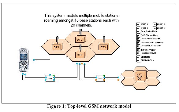
The top-level model is shown below (Fig.1); it consists of a mobile station (user) block, a collection of base stations, a base station controller and a wireless channel.
The Base Station Controller and Wireless Channel modules are control modules configured by model parameters. The Base Station Controller creates the base stations, coverage area and users. The Wireless Channel module moves users through the coverage, terminates calls, and removes users who have moved outside the coverage area or completed their calls.
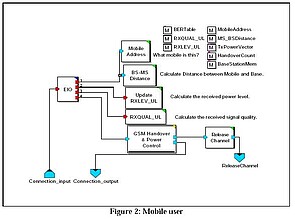
1.1. The Mobile Station Module
The mobile station block models the operation of a single user and contains some of the functionality of the GSM stack architecture. Although the top-level model shows a single mobile station , the model generates many users during the simulation. The user simulation process consists of creating users, initiating calls, moving users through the service area while calls are in progress, terminating calls, and removing the users. (Much of this process is handled by the base station controller.)
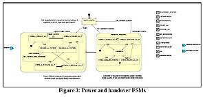
The GSM power and handover control block is modeled with Finite State Machines (Fig.3).
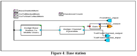
1.2. Base Station Module
The base station module contains modules to assign base stations and channels to users.
The AssignBaseStationToMobileUsers module assigns a Base Station to the Mobile User. The closest Base Station to the Mobile User is selected to serve the User. The module uses the x & y coordinates of the incoming Mobile User as well as the x & y coordinates of the Base Stations to compute the distances between the incoming Mobile User and all the Base Stations. The shortest distance determines the Base Station serving the Mobile User.
The AssignChannelifpossible module assigns an available channel of the serving Base Station to the Mobile User. If no channel is available, the Mobile User is blocked and exits the system prematurely.
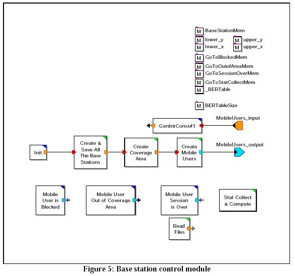
1.3. Base Station Control Module
The Base Station Control module contains blocks to create and save the base stations, create the coverage area, create the mobile users and collect statistics to document operation.
The Create and Save Base Stations module generates and saves all the Base Stations. The total number of Base Stations generated is b*b where b is specified by the Base Station Matrix Size parameter. The x & y coordinates of these Base Stations are generated based on the distance between the Base Stations (a parameter) and the initial Base Station's x & y coordinates (also parameters.)
The Create Coverage Area module creates the coverage area by computing the upper and lower limits on the x & y coordinates from the initial Base Station's x & y coordinates, the distance between the Base Stations, and the Base Stations matrix size.
The create users module generates Mobile Users with time between them exponentially distributed with mean specified by the parameter "Exp Pulse Mean". The Mobile Users are generated until the time value specified by the "Time To Stop Traffic" parameter is reached. User locations (x & y coordinates) are generated randomly inside the coverage area. The direction in which a Mobile User moves is randomly selected from the possibilities specified by the ?Direction of Motion? parameter. If this parameter is set to eight, then there are 8 possibilities: North, North East, East, South East, South, South West, West, and North West. If if it is set to 4, the possibilities are North, South, East and West.
The Statistics Collection collects statistics of the Mobile Users exiting the system during the simulation run and also computes the statistics at the end of the simulation run. It computes the percentage of Mobile Users exiting the system under the normal condition, under the no-channel condition and under the exiting the coverage area condition. It also computes the percentage of requested time supported by the system under the various different conditions.
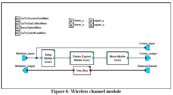
1.4 Wireless Channel
The Wireless Channel module contains blocks to delay mobile seers, delete expired mobile users and move mobile users.
The Move Users module determines the new position of the Mobile User. It uses the old x & y coordinates, direction of motion, and speed of motion. If the new position is outside the coverage area, the Mobile User can not use the system any longer and has to exit the system. The Mobile User's speed of motion and session length are both randomly selected using uniform distribution between the values specified by the "Minimum Speed Limit", "Maximum Speed Limit", "Minimum Session Length", and "Maximum Session Length" parameters. The time to exit is current time plus session length, however a Mobile User may exit the system prematurely by going outside the coverage area or by moving to a cell where the Base Station does not have an available channel.
2. Parameters
The model is very flexible and has a large set of configuration parameters.
|
|
3. Outputs
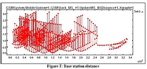
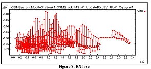
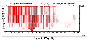
The selected outputs from this model are shown in Figure 7. The graph shows the distance between the mobile users and base stations during the simulation. The two graphs below show received signal power (Fig.8) and received signal quality (Fig.9) for the same simulation.