Mainnavigation
Subnavigation
BORDER
Pagecontent
- You are here:
- Home »
- MLDesigner »
- Examples »
- Wireless/Mobile Applications »
- Emergency Trunked Radio System
Modelling an Emergency Trunk Radio
System with MLDesigner, SatLab and Data Structures
This is a joint MLDesigner-SatLab model of an emergency services trunk radio system. It is comprised of fixed and mobile stations in the area around Pittsburgh communicating through a shared set of radio channels. A central control system controls access to the radio channels. The system is represented as an MLDesigner Discrete Event model. SatLab provides model support; it dynamically calculates the physical positions of all mobile nodes for MLDesigner and calculates the path loss for all pairs of nodes.
The mobile nodes are organized into fleets and subfleets, all of which are defined with data structures. This greatly simplifies the model because the number, organization and call behavior of the nodes can be defined via parameters rather than by changing the model. Parameters also define the number of channels, central facility locations, transmitter and antenna characteristics, noise estimates, etc.
The top-level model is shown below. The list to the right shows shared memory elements available to all blocks. The key blocks are Station Initialization, TRS communication and TRS wrap-up.
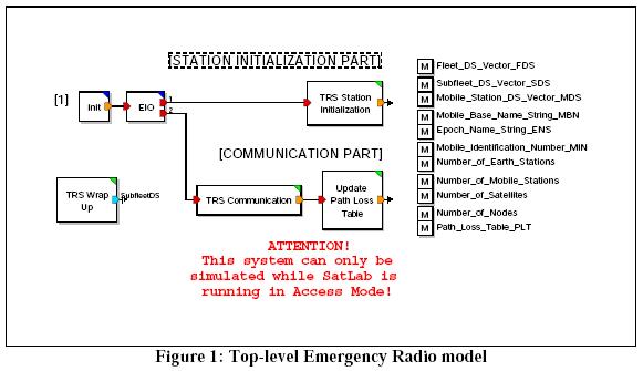
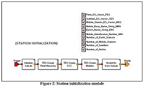
The initialization block (Fig.2) sets up the simulation, establishes connection with SatLab, establishes the central System Control Center and creates data structures to represent all the mobile nodes. When this is complete, operations start.
The Communications module (Fig.3) simulates the behavior of the system in operation. It generates call requests (Call Requests Source block), models the transmission of the call requests (Control Channel block), and models the processing of the call requests by the System.
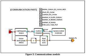
Central Controller
The Call Requests Source module generates call requests for the system. Transceivers within the system fleets originate these call requests during each fleet's active time. There are 14 fleets in this system; each with a different set of active and inactive periods. Some fleets have fixed active and inactive times other fleets have probabilistic active and inactive times. Active times can be modified by parameter.
During the active times of each fleet, fleet transceivers generate Poisson-distributed call requests (there are three different call generation patterns.) Call requests include a call holding time (exponentially distributed around a defined mean) and a ?time created? value.
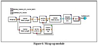
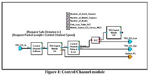
The Control Channel (Fig. 4) models the incoming call requests. It has two main blocks: Control Channel Collision and Control Channel Delay & Error.
The Control Channel Collision module detects collisions by calculating the difference between the "time created"of each incoming packet against the "time created" for the previous packet. If the time distance between the two packet arrivals is less than the time it takes to transmit the packet, both packets are marked collided and dropped.
The Control Channel Delay module delays the incoming packets by the time needed to transmit a packet (packet length/channel capacity.) It also calculates the probability of a transmission error and drops all packets with calculated transmission errors.
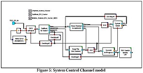
The SCC checks the ID state for subfleet generating the incoming call request. A subfleet ID can have one of four states: (1) Queue State [in the system queue waiting for an available channel.] (2) ActiveTrans State [holding and using a channel] (3) InactiveTrans State [holding, but not using, a channel-] (4) None State [no channel assigned.]
When a subfleet is in the Queue State or the ActiveTrans State, the SCC ignores incoming call requests. If subfleet is in the InactiveTrans State, SCC grants the inactive channel and shifts the subfleet to the ActiveTrans state. If the subfleet is in the None State, theSCC requests a channel and, if no channel can be found, places these call requests in the System Queue until channels are available. When a channel is released, the subfleet call request at the front of the System Queue is assigned the channel and the transceiver with the queued call request is given access to start using it.
When a transceiver is done with a channel, the channel remains assigned to the using subfleet and will be assigned to any subfleet member that generates a call request during the MTT period. At the end of the MTT period, the channel is released and returned to the channel pool so SCC can assign it to the next call request in the System Queue.
When the simulation completes, the wrap-up module closes the active elements and generates the statistical reports.
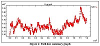
The graph below (Fig.7) shows a path loss summary for a simulated operation. To generate other statistical summaries, add the appropriate statistics block to the model.