Mainnavigation
Subnavigation
BORDER
Pagecontent
Crosslink Channel Analysis
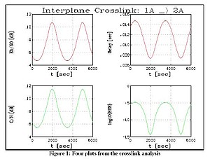
The plots and map below were generated with a SatLab crosslink channel analysis for the<br />Iridium satellite system. It could easily be modified to perform the same analysis on a different satellite system by changing the satellite configuration information.
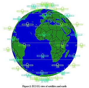
The map shows the Iridium satellites in an Earth Intertial GL view from space. The viewing perspective is directly above the equator at 0 longitude so satellites 1A and 2A, used in this analysis, are clearly visible in the southern hemisphere.
The script for this analysis is shown below.
%
%        This demo simulates the Iridium system. During the simulation
%        the interplane crosslink between satellite 1A and satellite 2A
%        is calculated. For this crosslink Eb/N0, delay, C/N, and the
%        biterror rate is calculated and shown.
%        The used frequency, coding, modulation, etc. can be changed
%        by the user in the m-Files.
%

1;  % Not a function file, since the first command is not the function keyword

function [EbN0, DELAY, BEP, CN, CN0] = CrossLinkChannel(DIST)

  %   DIST  [km]   Distance vector from groundstation to satellite
  %   ELEV  [deg]  Elevation angle vector from groundstation to satellite
  %   ALT   [km]   Altitude of groundstation over NN
  %   LAT   [deg]  Latitude of groundstation (deg)
  %
  %   EbN0  [dB]   Bit energy Eb/N0 (dB)
  %   DELAY [sec]  Delays
  %   BEP   []     Bit error rate
  %   CN    [dB]   Carrier-to-noise ratio
  %   CN0   [dB]   Carrier-to-noise density ratio (dB)

  % user setting variables for downlink
  F     = 1.62e9;   % Carrier Frequency [Hz]
  B     = 10e6;     % Channel Bandwidth [Hz]
  Rb    = 12e6;     % Data bit rate [bps]
  Eta   = 0.55;     % Antenna efficiency
  D     = 2;        % Antenna diameter [m]
  Pt    = 1;        % Transmitter Power [W]
  Lp    = 3;        % Pointing Loss [dB]
  ISI   = 0.5;      % Intersymbol Interference Loss [dB]
  Lm    = 3;        % Link Margin [dB]
  Fomr  = -10;      % Figure of Merit [dB]
  Coder = 4;        % ConvolutionCode4
  M     = 17;       % QPSK modulation
  Gt    = G_antenna(F, D, Eta); % Antenna gain maximum
  EIRP  = dB(Pt) + Gt;          % EIRP
  Lfs   = L_fs (DIST, F);       % Free space Loss
  L     = Lfs + Lp + ISI;       % Overall Losses
  Gc    = G_coding (Coder);

  [EbN0, CN0, CN] = LinkBudget(EIRP, L, Lm, Gc, Fomr, Rb, B);
  DELAY = Delay (DIST);
  BEP   = BER (EbN0, M);

  % inverse dB
  EbN0A = exp10(EbN0/10);

endfunction


%
% start of the demo
%

fprintf(stdout,"Start of introductory demo_channel_updown.....\n");

% Load system Iridium
fprintf(stdout,"Loading the Iridium system\n");
fprintf(stdout,'loadreplaceAll("./IR66.data");\n');
loadreplaceAll("./IR66.data");
dt = 100;
i  = 0;

setSimEpoch(1996,7,29,14,30,0);
setSimStepSize(dt);

[lon,lat,alt] = getNodeParameter ("SanFrancisco", P_lon, P_lat, P_alt);
for t=0:dt:6000
  i       = i+1;
  time(i) = t;
  stepSim;
  [DIST(i),RELVEL(i),AZ(i),EL(i), V(i)] = RelPosition('1A','2A');
endfor

[EbN0, DELAY, BEP, CN, CN0] = CrossLinkChannel(DIST, EL, alt, lat);

% plot the result
t=0:100:6000;
erase

title('Interplane Crosslink: 1A -> 2A');
window('221');
plot(t,EbN0,'grid','red');
xlabel('t [sec]');
ylabel('Eb/N0 [dB]');

window('222');
plot(t,DELAY,'grid','red');
xlabel('t [sec]');
ylabel('Delay [sec]');

window('223')
plot(t,CN,'grid','green');
xlabel('t [sec]');
ylabel('C/N [dB]');

window('224')
plot(t,log(BEP),'grid','green');
xlabel('t [sec]');
ylabel('log10(BER)');

demos
%endfunction