Mainnavigation
Subnavigation
BORDER
Pagecontent
- You are here:
- Home »
- MLDesigner »
- Examples »
- Networking Applications »
- Three Optical Pixel Bus Networks
Three Optical Pixel Bus Virtual Prototype Networks
Exploring Design Alternatives
This application note shows how MLDesigner can be used to evaluate alternative design approaches early in the design process. Three different pixel bus network design were developed to explore different approaches to next-generation optical networks. Pixel bus networks carry a constant stream of sensor-generated data to control and display devices.
The three system-level models are used to:
- Analyze performance and cost implications of design alternatives
- Demonstrate network operations for each of the alternatives via control panels that provide dynamic control over key system parameters and provide immediate visual feedback for parameter changes
These three virtual prototypes were developed with a prototype MLDesigner optical network components library. The MLDesigner Optical Components Library is a collection of Discrete Event data structures and building blocks for the design and performance analysis of optical networking components and systems. The blocks can be combined to create models of optical network components (e.g., switches) and add optical interfaces to computer and server modules. The resulting models can be combined with upper layer protocol modules to do complete end-to-end optical network models.
The MLD Optical Components Library includes special optical library data structures, low level building blocks (e.g. laser sources, couplers, switching elements), high level building blocks (e.g., MUXers and DEMUXers, switches, inverters) and some sample optical system models (e.g., switched and switchless TDM and WDM Pixel Bus systems.
Physical layer models developed with the Optical Components Library can be extended with components from other MLDesigner libraries to model all layers of the OSI stack.
Pixel Bus Broadcast and Select System in DE Domain
This system represents a four-channel broadcast and select network operating at 2.5Gbps. Each of the four channels is transmitted on a separate DWDM wavelength and then coupled onto a single fiber. The WDM signal is split, and the receivers can be tuned to receive any of the four channels.
The data input into the system is a stream of integers indicating the channel. For instance, Transmitter 1 (channel 1) is given a stream of integer 1's as data, Transmitter 2 is given a stream if 2's, and so on. This is for demonstration purposes to make channel switching evident on the output graphs. In future the integer data will be replaced with more realistic data streams.
The Control Unit provides centralized electrical control of the optical network and determines<br />which wavelength will be received by each optical receiver. The Control Unit reads control information from a predefined control file and sends new instructions to the system every 5 clocks.
The Power Probe modules will read the optical power level of the Single_OL data structure as it travels through the system. The optical power values are written into a text file. After a simulation this text file can be imported into a spreadsheet program to produce a graphical representation of the optical power loss through a link.
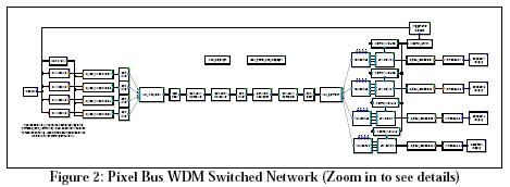
Pixel_Bus_WDM_Switched System in DE Domain
This system is similar to the WDM Broadcast and Select Pixel Bus. In place of the tunable optical receivers are fixed wavelength receivers. The channels are selected by the bank of demultiplexers and optical switches. This setup while requiring more equipment may be more economical due to the high cost of tunable optical receivers. The system operates at 2.5Gbps.
The data input into the system is a stream of integers indicating the channel. For instance, Transmitter 1 (channel 1) is given a stream of integer 1's as data, Transmitter 2 is given a stream if 2's, and so on. This is for demonstration purposes to make channel switching evident on the output graphs. In future the integer data will be replaced with more realistic data streams.
The Control Unit provides centralized electrical control of the optical network and determines which wavelength will be received by each optical receiver. The Control Unit reads control information from a predefined control file and sends new instructions to the system every 5 clocks.
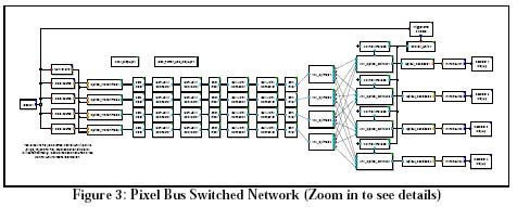
Pixel Bus Switched Network
In this system, a four-channel pixel bus is created using a separate fiber for each channel (no WDM). This is done to explore the possibility of using lower cost multimode components. The signaling rate of the system is limited to 1.0 Gbps. A bank of splitters and optical switches are used to provide each receiver access to all of the channels. The data input into the system is a stream of integers indicating the channel. For instance, Transmitter 1 (channel 1) is given a stream of integer 1's as data, Transmitter 2 is given a strewn if 2's, and so on. This is for demonstration purposes to make channel switching evident on the output graphs. In future the integer data will be replaced with more realistic data streams. The Control Unit provides centralized electrical control of the optical network and determines which wavelength will be received by each optical receiver. The Control Unit reads control information from a predefined control file and sends new instructions to the system every 5 clocks.
Model Outputs
All three models have similar data outputs, however they can also be configured to operate with Control Panels.
Data Outputs
Data outputs provide both receiver and system information.
Receiver Information:
- Received Data
- Average Latency
- Average Power Margin
- Latency for each Single_OL
- Power Margin for each Single_OL received
System Information:
- Electrical Power Use
- System Cost
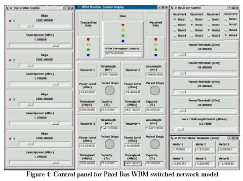
Animation
This control panel was created for use with the WDM Pixel Bus model using components from the MLDesigner TclTk animation and dynamic control toolkit. Sliders on the left side of the panel configure transmitters (data rate, launch power.) Sliders on the right (center) configure receivers (power threshold.) Center readouts report channel status and activities. Readouts at the bottom right report data from power meters positions at different points in the network.


