Mainnavigation
Subnavigation
BORDER
Pagecontent
- You are here:
- Home »
- MLDesigner »
- Examples »
- Networking Applications »
- Network Concentrator
A Network Concentrator
Concentrator multiplexes multi-media traffic sources into a single channel
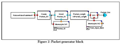
This concentrator system model buffers packets received from multiple sources and outputs them on a single transmission channel. The concentrator consists of packet generators, packet buffers, the concentrator itself and support blocks.
The top-level block diagram is shown below.
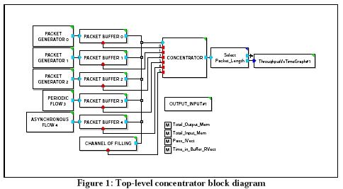
There are three packet generator variations. Packet generators 0, 1 and 2 all generate packets following a Poisson distribution; the other two packet generators follow a uniform distribution. All packets are of fixed length (specified by parameter) and have unique ID numbers.
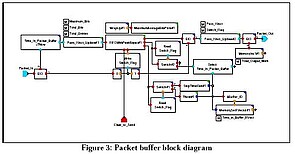
The packet buffers (Fig.3) are FIFO queues and can be accessed simultaneously for both read and write. Reading and writing rates may not be equal. Buffer parameters define buffer size, priority order (used by the concentrator) and the maximum time packets can remain in the buffer. The packet buffer sends four flags to the concentrator:
- OUT_OF_TIME : A packet in the buffer is out of time
- HALF_FULL: The buffer is half full
- PTO: The number of bits in the buffer is less than the length of a frame
- EMPTY: The buffer is empty
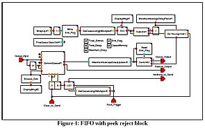
The FIFO with peek is the key element of the packet buffer (Fig.4).
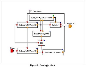
The concentrator controls buffer transmission based on the flags received. Concentrator make four passes through the flags in the following order:
- Pass 1: OUT OF TIME
- Pass 2: HALF_FULL
- Pass 3: EMPTY
- Pass 4: PTO
On each pass the concentrator looks at buffers in decreasing priority. If no buffer satisfies the condition for that pass (e.g., OUT_OF_TIME) the concentrator moves to the next pass. If all four passes are completed and no buffer is selected, then channel filling is selected. After buffer selection, the concentrator begins again with pass 1.
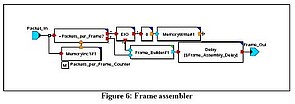
The concentrator frame has a fixed length and can hold up to six packets. The frame is padded if there are not enough packets to fill it.
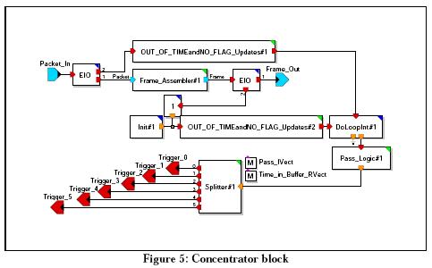
The frame assembler and pass logic blocks from the concentrator are shown below.
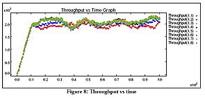
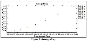
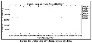
Three outputs from this model are shown below: a throughput vs time graph, an average delay graph and an output/input vs frame assembly delay.