Mainnavigation
Subnavigation
BORDER
Pagecontent
- You are here:
- Home »
- MLDesigner »
- Examples »
- Control Applications »
- TTP Bus Model
A TTP Bus Model
Bus access using the TTP (Time-Triggered Protocol)
This example shows bus access using the Time-Triggered Protocol TTP/C. It supports a static TDMA schedule, membership & acknowledgment services, and clique avoidance. As yet synchronization algorithms, bus guardians, and the possibility of mode changes are not implemented. The model consists of the basic components needed to add TTP to an existing model (channel, controller, host) and an example system model. The host block is an example that can be modified as needed.
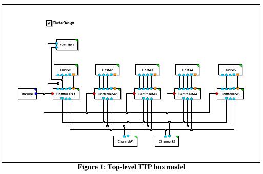
The Model
The top-level TTP model is shown below. It consists of two TTP/C bus channels, five TTP controllers and their associated hosts, a statistics module, and a cluster design memory. The cluster design, also known as the 'abstract MEDL' (MEDL – Message Descriptor List), describes the communication pattern of a cluster. It defines the TDMA round layout, that means the number of slots per TDMA round, the number of TDMA rounds per cluster cycle, nodes which are allowed to send in a slot, and the duration of slots and transmission phases in macroticks.
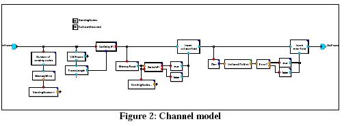
TTP Bus Channels
In general a TTP bus consists of two independent channels. The model of a simple channel is shown below. All incoming packages are delayed by the frame length defined within the data structure describing the packet. (A channel delay is not supported until a synchronization algorithm is implemented.) The module recognizes collisions and transmission errors and marks appropriated flags within the frame. Transmission errors are uniformly distributed with a given frame error rate defined by parameter.
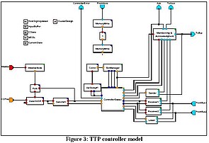
TTP Controller Module
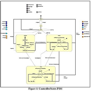
The major components of the TTP bus are the instances of controller model shown in figure 3. The current protocol state is managed by the FSM 'ControllerStates' shown below. Possible states are Freeze, Init, Listen, Passive, Active, and ColdStart.
After node initialization the controller sends cold start frames or listen for received cold start frames or TTP frames (in this implementation all frames contain explicit CStates) to integrates on it. During this cluster startup the 'SlotManager' starts the timing according to the defined TDMA layout. It triggers the 'ControllerStates' model at the begin of receiving or sending slots and at the end of transmission phase. After cluster start has finished the controller can send and receive TTP frames. When 'ControllerStates' is triggered at port 'InATSender' clique avoidance and communication blackout tests are requested to model 'Membership & Acknowledgment'. If one of the checks fails, the controller freezes. In other case if the controller is in active state the'Sender' model creates a TTP frame which contains the CNI frame stored in the input buffer memory and send it over module 'Membership & Acknowledgment' to the TTP/C bus. When the model 'Receiver' is triggered at port 'ActionTimer' it listen on TTP/C channel until receiving trigger on input port 'EndOfTP'. After this the module checks the received frame for transmission errors and failures and send the frame to 'Membership & Acknowledgment' for CState agreement test. At the same time membership & acknowledgment services are performed. The CNI (Communication Network Interface) is realized by the ports 'Ack', 'COFlag', 'ControllerError', 'FromHost', and 'ToHost'. 'FromHost' and 'ToHost' offer the frame communication between controller and host. 'Ack' is fired by the controller if the decision phase for acknowledgment of the last sent frame has finished. An observed controller error (clique error, communication blackout, maximum acknowledgment failurre) is sent to host over port 'ControllerError'. The host can restart or freeze the controller by firing the 'COFlag' port.
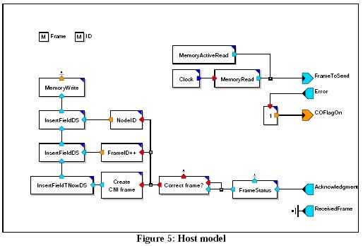
The Host Module
A very simple example of a host model is shown below. The model sends CNI frames with constant interval, given by parameter 'SendInterval', to the controller. The frame information (frame identification, creation time) is updated after receiving positive acknowledgment. If the host observes a controller error the host restarts the controller at the same time.
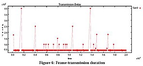
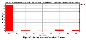
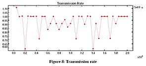
The Statistics Module
The 'Statistics' model outputs the current transmission rate of a node during simulation. Results displayed after simulation are shown below.