Mainnavigation
Subnavigation
BORDER
Pagecontent
- You are here:
- Home »
- MLDesigner »
- Examples »
- Computer Architecture »
- Multiprocessor
Multi-Processor Computer Architecture Model
Modeling high-level behavior and performance of a multiprocessor system
This flexible model was developed to demonstrate techniques for modeling high-level behavior and performance of multi-processor computer architecture. The model uses independent software and hardware models that interact through a shared memory virtual connection.The software part models the Procedures, Queues, and Locks needed to model execution of software instructions. The hardware part models the behaviors of various hardware components and interactions between them. Parameters control key design elements such as Processor Speed, Instructions per time unit, Mean Memory Accesses Per Instruction, Cache Hit Rate, Bus Cycle Time, Number of Processors, and Memory Access Time. Embedded probes collect performance data and display it as raw data or graphical summaries either dynamically during execution or as post simulation summaries.
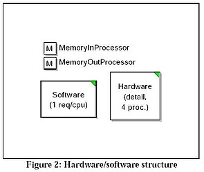
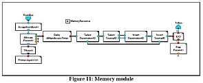
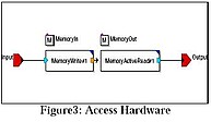
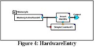
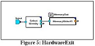
The AccessHardware block represents the software layer and the Hardware Enter and HardwareExit blocks represent the hardware layer. Instructions flow from the software module (not shown) into the AccessHardware module, which places them in the MemoryIn block. HardwareEnter accesses the instructions and passes them to the hardware module (not shown) for execution. The hardware module returns completed instructions to HardwareExit which transfers them to MemoryOut, where they are read by the Access Hardware block and passed back to the software module. The three figures below show this in more detail.
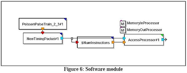
The software module abstracts the operating system and application as a series of procedure requests that are scheduled to run on the CPUs (see below). The software module generates processor requests, one at a time, to the hardware. The processor request is modeled using an efficient MLDesigner hierarchical data structure that specifies the number of instructions associated with the processor request as one of its fields. Another data structure field holds a Timing Packet data structure to keep track of the timings in different stages of processor execution.
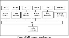
The hardware model (see below) is comprised of four Central Processing Units (CPUs), each with an associated Cache Memory, connected to a Bus-type interconnection network. Each CPU can independently send requests to the bus for accessing the Main Memory and can send/receive requests and responses to and from I/0 devices like disk and network controllers. When the hardware model receives a processor request, Dispatch looks for an idle CPU. If there is an idle CPU, Dispatch sends the request to that CPU and marks that CPU busy. Otherwise, Dispatch queues the request until a CPU becomes available and then dispatches it and marks the CPU as busy. At the completion of request processing, the CPU returns the request to the Dispatch module where the Free module releases the CPU and request is returned to the software layer.
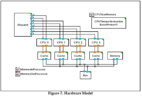
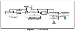
The CPU module decides which instructions require access to memory, requests that number of memory accesses to the Cache module and waits for the response from the Cache module. When the CPU module receives the response from the Cache module, it inserts a delay to account for the CPU execution time for that instruction. When all the instructions for a particular CPU have been executed, the Processor Request DS is returned to the Dispatch module. If there are more queued processor requests, they will be sent for processing.
The Cache decides if the memory request can be filled or requires main memory access. If main memory access is required, the request is passed to the bus; if not, the Cache adds a delay to represent cache access and passes the memory request back to the CPU. CPU picks the data. Otherwise, the CPU accesses main memory through the bus to pick the data and to fill the cache.
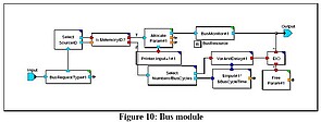
The Bus module receives cache line fill request from the cache and if the bus is in use, the cache line fill request is queued. If the bus is free, the Bus module grabs the bus and sends the BusDS data structure to the main memory. The Bus module holds the bus until it receives a response from the main memory and applies a delay to account for the bus delay. Once the delay is over, the Bus module frees the bus and returns the BusDS to the Cache module.
Note: A 20-page white paper describing this model is available. Model developed by Dr. Keyvan Farhangian of KVON Technologies.