Mainnavigation
Subnavigation
BORDER
Pagecontent
- You are here:
- Home »
- MLDesigner »
- Examples »
- Wireless/Mobile Applications »
- Rake Receive Model for WCDMA
A Rake Receiver Model for WCDMA Studies
Analyze and Evaluate Rake Receiver Design
This Dynamic Data Flow model was developed to do WCDMA modulation/de-moduation studies. The top-level model is shown below.
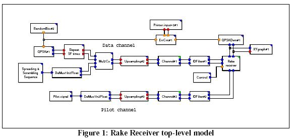
This is a flexible model that can be reconfigured to perform a variety of studies such as BER analyses for different system configurations. The model is extensively parameterized, so system configurations can be changed easily and quickly.
The key modules in the top level model are the rake receiver, the channel model. (Modules contain block diagrams and have green upper right corners.) Other functions are realized with primitives. (Primitive blocks contain C++ code and have blueupper right corners.) The Spreading & Scrambling Sequence and Pilot signal blocks read data from input files and pass them on to their respective DeMux blocks.
The Upsampling block repeats each input sample a specified number of times for every pair of input-output ports.
The IDFilter block integrate inputs samples over Oversampling samples.
The Control block is a waveform primitive that outputs a waveform as specified by the array state "value" (default "1 -1").
The Rake Receiver module is a demodulator for a DS-CDMA signal stream. It is comprised of several custom primitives, augmented by standard MLDesigner SDF/DDF primitives.
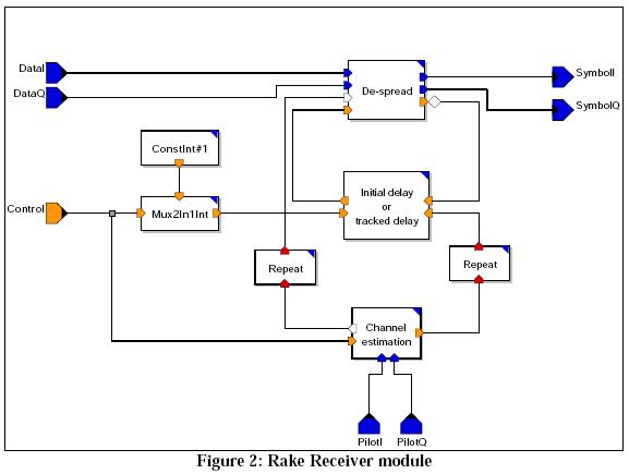
The Rake Receiver module implements the demodulation of a DS-CDMA spread signal of one user, including channel estimation and maximum ratio combining of 'NumberOfFingers' phase corrected multi-path components. In one step the model reads 'BlockLength' * 'Oversampling' samples from the I and the Q branch of the incoming data signal and calculates 'BlockLength'/'SpreadingFactor' symbols. During the demodulation, a time-tracking of finger delays is done.
If the parameter at the control port is set to one, the delay, phase shift, and channel power of every multi-path is estimated before demodulation by analyzing the known pilot signal. The output results of the rake receiver are zero until the control bit is set to one the first time.
The De-spread block reads 'SpreadingFactor' * 'Oversampling' samples from the I and the Q branch of the incoming data signal, de-spreads 'NumberOfFingers' multipaths, and combines the results coherently by using maximum ratio combining. At each step the primitive reads the estimated phase shift, channel power, and delay of multi-path components from the input ports 'Phasor' and 'InDelay'. The estimated phase shift and channel power are used for the phase correction and as factor for maximum ratio combining within the rake. The delay is used for the correct despreading of all multi-paths. In addition a time synchronization is implemented. This is done by the early-late gate synchronizer with a timing offset half the chip duration. The time-tracked delays are sent to the output port 'OutDelay'.
The Channel Estimation block reads 'LengthPNSequence' + 'MaxDelay' * 'Oversampling' samples from the I and the Q branch of the received pilot signal. If the value of the input port 'Control' equals one, the phase shift 'power' and 'delay' of the 'NumberOfFingers' strongest peaks of the cross-correlation with the reference signal are computed. Otherwise the results of the previous estimation are output.
The Initial Delay or Tracked Delay block sends the values received at one of two integer inputs to the output port based on a control parameter.
The Repeat blocks repeat each input sample a specified number of times for every pair of input-output ports.
The Channel Model consists of a collection of primitive blocks. The channel model processes the received signal by injecting defined delay, rotating the complex values by defined constant angle values, adding defined gain, summing the complex inputs and then adding White Gaussian Noise to the signal. Delays, rotation angles and gains are defined by parameters.
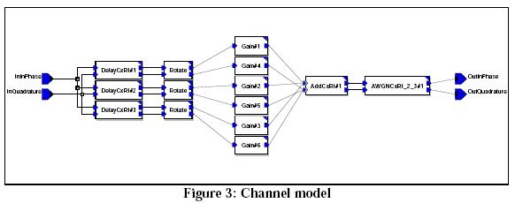
The delay blocks delay the complex input(s) for the number of cycles specified by a parameter. The rotation blocks rotate the complex inputs by a parameter-defined angle. The gain block then multiplies the complex inputs by a defined gain factor.
The AWGNCxRI block adds white Gaussian noise to the values received at the input ports InReal and InImag. The mean of the Gaussian noise process is zero. The variance is equal to the power of the Gaussian noise which is computed by
Factor * pow(10,(-SNR/10)) * SignalPower,
where SNR is the Signal-to-Noise Ratio in [dB]. SignalPower is the power of the signal in [Watt], and Factor is used to scale the SNR. The parameter SignalPowerFlag determines whether variance of the Gaussian noise process is determined by the parameter Signal Power or from the input values during the simulation run.
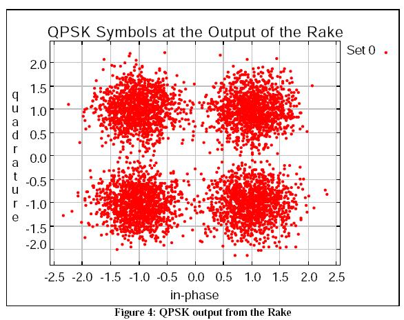
As configured, the model generates an XY plot showing the QPSK signals at the output of the Rake Receiver.
The signal data can also be written to a file for post-simulation analysis.