Mainnavigation
Subnavigation
BORDER
Pagecontent
- You are here:
- Home »
- MLDesigner »
- Examples »
- Wireless/Mobile Applications »
- GSM/GPRS Network Simulator
The GSM/GPRS Network Performance Simulator
Analyze the Performance of a GSM or GPRS Cellular Network Design
Overview
The Mission Level GSM/GPRS Network Performance Simulator (MLNPS) is an MLDesignerapplication to analyze the performance of a GSM or GPRS cellular network design.The MLNPS simulates GSM and GPRS network operations by configuring a simulationmodel of the network (importing the network layout, setting the GSM/GPRS algorithm-related parameters.) generating a simulated user population, and then testing thenetwork model with the simulated user population. The number and type of users (fixed,walking or automotive passenger), types (voice or data) and duration of calls are controlledby parameter. The MLNPS automatically collects data describing the behavior ofthe system and the outcomes of user calls. It displays a series of performance graphs thatreport data such as uplink/downlink RX power, uplink/downlink channel interferencedata transmission rate and block error rate. The MLNPS model can be easily modified toadd new statistics that can be written to files or summarized in graphs.
The MLNPS has many potential applications such as:
- Designing physical network layout, including positioning and configuring base stations, based on use scenarios. New use scenarios can be easily imported intothe simulator. The MLNPS is equally at-home with commercial networks, private networks and military networks.
- Assessing the impact of network tweaks and configuration changes. These changes could include “hard” changes (Base station location, coverage patterns, power levels) or “soft” changes (control algorithms such as channel allocation, handover or resource allocation).
- Analyzing the impact of and pricing Mobile Virtual Network Operator (MVNO) services and agreements.
- Assessing the impact of new 2.5G and 3G wireless services (such as e-mail, messaging, multimedia, positioning) on existing or proposed wireless networks.
- Extension to other wireless protocols such as TDMA, WLAN/WiFi (802.11) and 2-way radio.
- Defining requirements for network components such as base stations, handsets. MLDesigner can be used to generate a high-level executable specification of these components and do a performance analysis of the design in the context of the complete MLNPS model.
- Demonstrating wireless component (base station components, handset components, implemented algorithm changes, service profiles (or proposed component) performance in use context.
- Development and testing of new implementation algorithms.
- Links to other programs, such as Planet.
Configuration
For ease of understanding, the MLNPS model can be divided into four parts: Environment setup, network configuration, user definition and simulation control.
Environment setup defines the physical characteristics of the network. The service area (zone) is defined (map, scale, streets, major buildings and other information), such as the granularity of the service area map. Base stations are defined (position on the map, the base station configuration variables such as number of dedicated voice, data and handover channels, maximum transmission power, etc.)
Network configuration defines the operational characteristics of the network such as TRX configuration, power control, host algorithms, the maximum users per channel, the handover algorithm and the frequency-hopping algorithm.
User definition specifies the user population. Variables include the number of users, the user type (fixed, walking or in a car), the physical movement associated with each user type, the call behavior (probability of initiating a call, probability of voice or data call, length of call), maximum handset power, etc.
Simulation control sets variables specific to the simulation run such as the amount of time to be simulated, the names of files where the output data are to be stored, etc.
Major Parameters
Model system configuration parameters include:
- The distance between two points in the service area in meters
- The number of Base Stations (BS) in the system
- The number of channels dedicated for handover within a BS
- The maximum number of users in the system
- The average session length of a voice call (unit: second)
- The call arrival rate
- The number of channels dedicated for voice call users within a BS
- The number of channels dedicated for GPRS users within a BS
- The probability of creating voice call (as opposed to a data call)
- The maximum number of users in a channel
- The maximum Transmission Power of a Mobile Station in dB
- The maximum Transmission Power of a Base Station in dB
- The probability that the block is transmitted incorrectly
- The interval of events in seconds
- The type of interference measure to be used (co-channel interference, adjacent frequency interference or both)
- Half Rate voice call (on or off)
- Frequency Hopping (on or off)
- The types of users (allocate among fixed, walking or automotive)
- The size of the service area
- Pointers to files holding the service area map, map index, street and building information
(Individual modules have additional configuration parameters.)
Model structure
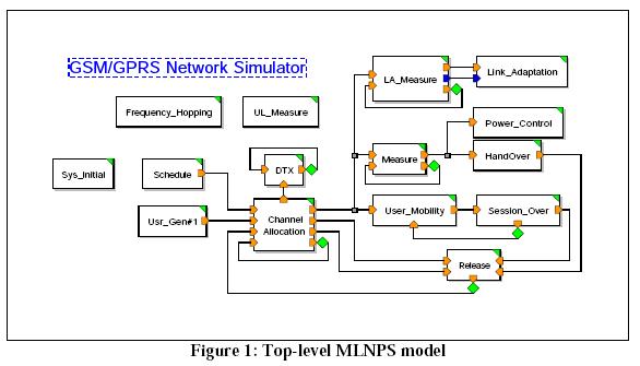
The model is comprised of hierarchical modules, as shown in the screen shot below.
The top-level modules include:
- System_Initial Module. This module initializes system parameters that define the service area, base stations and users.
- Channel Allocation Module. This module allocates channels for both voice call users and packet date users.
- Discontinuous Transmission Module.
- LA_Measure Module. This module calculates the mean Block Error Rate for each filtering period during the simulation.
- Link_Adaptation Module. This module changes the coding scheme every filtering period.
- Power Control Module.
- Handover Module. This module manages the handover process.
- Mobility Module. The module calculates position data for walking and automotive users.
- Session Over Module. This module does housekeeping at the end of the simulation.
- Release Module. This module closes the simulation.
- Schedule Module. This module organizes operation.
- Measure Module. This module measures mean uplink/downlink values of RXLEV, C/I and MS-BS distance.
- UL_Measure Module. This module measures the channel interference values for uplink channels.
- Frequency Hopping Module. This module handles frequency hopping during the simulation.
- Create_User Module. This module creates the user populations for simulations.
- User_Initial. This module defines user characteristics.
Each of these modules is, in turn, comprised of lower level modules and/or primitives.
Outputs
Output graphs include:
- Data Transmission Rate
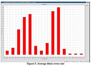
- Average Block Error Rate
- Down link received power level
- Up Link received power level
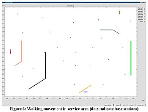
- Walking user movement in service area (relative to XY coordinates and base station positions)
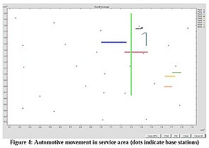
- Vehicular user movement in service area (relative to XY coordinates and base station positions)
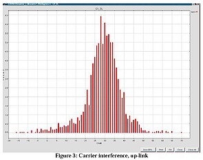
- Carrier interference-uplink
- Carrier interference-down link
- Down link interference
Sample outputs are shown on the following pages.
Note: This model was developed by Siemens AG.

