Mainnavigation
Subnavigation
BORDER
Pagecontent
- You are here:
- Home »
- MLDesigner »
- Examples »
- Networking Applications »
- Office Model
The Office Model
A simple network model in MLDesigner
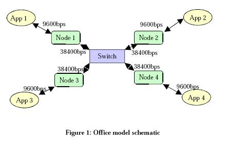
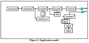
The office model demonstrates how to build a simple network model (see schematic in Figure 1) in MLDesigner.
Main features of the office model are:
- All applications transmit 1056 bit packets at the same rate of 8 Hz but the destination is random
- Applications to and from Node at 9600bps
- Node to and from Switch 38400bps
- TxQ service rate 7500 bps (flow control 7.1 packets/sec)
- RxQ service rate 9600bps
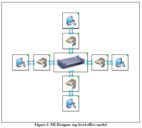
The MLDesigner Office model consists of three blocks--application (the computer icon), node (cable icon) and switch (see Figure 2).
Key model parameters include
- packet frequency
- packet length
- channel speed between application and node
- Number of applications
- TxQ
- RxQ
- Channel speed--node to switch
The application block contains a transmit path and a receive path. The transmit path creates data structures to represent the packets and passes them to the transmission block, which models the channel between the application and the node. The receive path receives incoming packets from the node and calculates statistics on them.
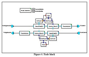
The Node block checks the length of the packet and then applies a delay calculated from the length of the packet and the channel speed. The node block has transmit and receive paths. The node block transmit path queues the packets received from the application (done in the services block) and then sends packets from the queue to the switch via the transmission block (same one used in application) which delays the packet by the time required to transmit to the switch. The node block receive path does the same time in the other direction (transmit and receive paths in the node are identical) . The node block also calculates node statistics.
Note that the transmit and receive queues are modeled with resources.
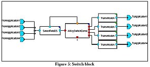
The switch block (Fig.5) consists of a switch primitive, a block to check the destination address in the data structure, and transmission blocks to represent the channel delay from the switch to the destination node. No statistics are calculated in the switch. The model does not include a formal flow control mechanism, but one could be added.
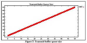
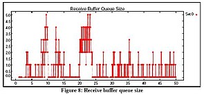
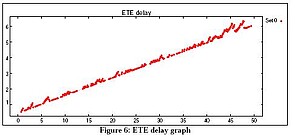
Statistics graphs are automatically generated. Samples of summary statistics graphs are shown below. Dynamic graphs can be added.
Node blocks generate transmit and receive buffer queue size graphs such as the ones shown in Figures 7 and 8.