Mainnavigation
Subnavigation
BORDER
Pagecontent
- You are here:
- Home »
- MLDesigner »
- Examples »
- Networking Applications »
- Flexible Switching Fabric Model
A Flexible Switching Fabric Model
3-layer networking fabric for analysis of complex network switches
This flexible model of a 3-layer switching fabric can be configured to represent fabrics of different size. The model provides a single instance of each switch and processor and generates additional instances as specified by configuration parameters.
The system consists of:
- Input Processors
- First layer switches (S1)
- P1 Processors that link S1s to S2s
- Second layer switches ( S2)P2 Processors that link S2s to S3s
- Third layer switches (S3)
- Output Processors, and a
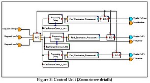
- Control Unit.
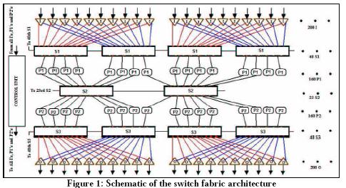
In operation, an Input Processor (I) receives packets, processes it and contacts the Control Unit to get the address of a processor (P1) to which the packet should be forwarded. The control unit knows which P1 is free or least loaded and sends the appropriate header information to I. Each Input Processor is connected to two S1 switches and a S1 switches are connected in a Ring Topology, so a packet from any Input Processor can be sent to any P1 processor. Each S1 is connected to 4 P1 processors. Switches at each level (S1, S2 and S3) read the header of the packet and forward to the next switch or the next processor. P1 processors receive packets, process them and then contact the Control Unit to get the address of the optimal P2 processor, insert the header and forward the packet to S3 for delivery to the appropriate Output Processor, which forwards the packet to the appropriate port without Control Unit intervention.
The schematic below shows the basic structure of the fabric.
The top-level MLDesigner model is shown below (Figure 2).
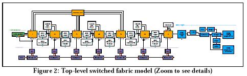
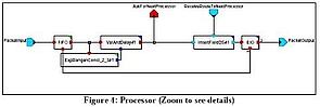
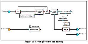
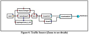
The key components: Control Unit (Fig.3), processors (a single model is used for all four processor types) (Fig.4), switches (a single model is used for all three switch types) (Fig.5) and the traffic source (Fig.6) are shown below.
Model parameters are shown below.
Top Level Parameters:
- Number of inputs, outputs
- Services rates for inputs, outputs
- Number of S1s connected to each input
- Number of inputs per S1 (S2, S3)
- Number of S1s (S2s S3s)
- Number of outputs per S1,S2,S3
- Service rates for S1,S2,S3,P1,P2
- Number of P1s,P2s
- Packet arrival rate
- Service rate of Control Center
- Maximum queue size
- Average calculation start time
- Processing delay
Switch Parameter:
- Service rate
Processor Parameters:
- Processing delay
- Maximum queue size
Traffic Source Parameters:
- Creation interval
- Traffic stop time