Mainnavigation
Subnavigation
BORDER
Pagecontent
- You are here:
- Home »
- MLDesigner »
- Examples »
- Satellite Applications »
- Air Traffic Management System
An Air Traffic Management System Model
Mission level model of Air Traffic Management (ATM) over Low Earth Orbit (LEO) satellite system
A mission-level model of a satellite-based Air Traffic Management (ATM) system uses an imaginary network of 20 Low Earth orbit (LEO) satellites and 11 ground stations to move control and data traffic between ground control stations and aircraft. The network carries messages for multiple services including Air Traffic Services, Airline Operation Control, Airline Administrative Communications, Airline Passenger Correspondence, Controller-Pilot Data Link, Datalink-Flight Information Services, and automated position reporting. A high-level diagram of the system is shown in Figure 1.
The Aircraft are modeled dynamically in MLDesigner with data structures and position data provided by SatLab.
- Flights are defined with a vector that includes flight name, departure and destination latitude and longitude, Altitude, start time, flight duration, takeoff time, route sectors and reporting interval.
- Each message service has defined message scripts that include sender ID, message sizes and message frequencies.
- Flights are divided into 10 phases, each with a defined length (en-route times vary), and each phase has a message service profile.
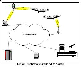
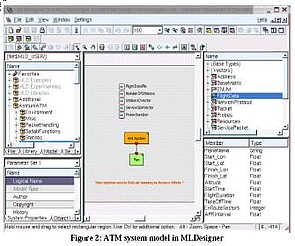
Figure 2 shows the top-level view of the ATM system model in the MLDesigner workspace (center of the GUI.). At this level the system is abstracted into two blocks - an initialization block that loads all start-up data files, and a run module. This model makes extensive use of shared memory modules to pass data between blocks. The five top-level shared memories are shown at the top of the block diagram. Other GUI windows show (clockwise from lower left) model properties, file manager, data structure editor, data structure members and, at the right bottom, the command window. The center right window shows the members/fields of the data structure used to move flight data through the model.
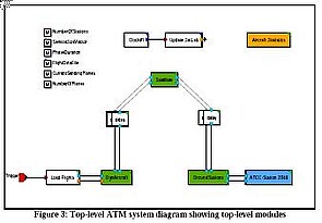
Figure 3 shows the Run module from the top-level block diagram shown in Figure 2. The blocks represent top-level functions (clockwise from lower left) loading flight data, dynamic aircraft (represented with data structures), transmission delay, the satellite system, transmission delay, ground stations and a control station. Top center blocks maintain the link to SatLab; the upper right block handles statistics collection and reporting. All the high-level blocks (defined with green upper right corners) contain hierarchical block diagrams that describe their functions in greater detail.
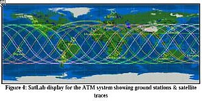
During each phase of a flight the model generates both ground and aircraft messages and sends them through the system as data structures. SatLab generates the positions for the satellite constellation and provides data for calculating the distances between the aircraft, the available satellites, and the appropriate ground stations. The SatLab-generated map (Figure 4 ) shows the ground stations and satellite routes.
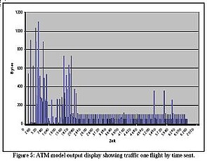
This model uses built-in MLDesigner analysis blocks to generate a variety of performance and behavior statistics. Figure 5 shows a profile of messages generated for a simulated flight.